Overview
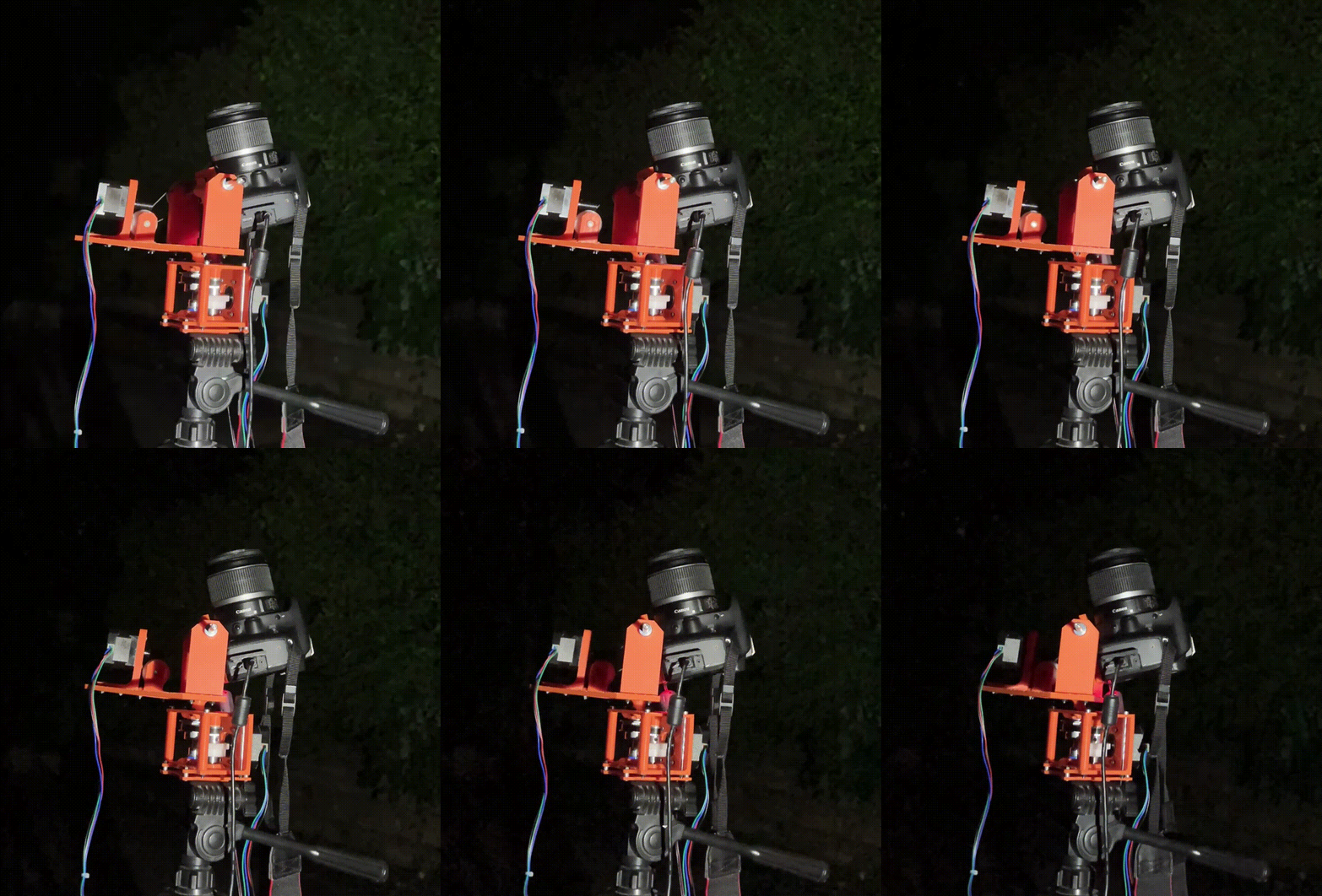
To capture detailed images of stars in the night sky, cameras need very long exposure time to collect as much light as possible. However, the Earth rotates too fast for these long exposure times, resulting in blurry streaks instead of sharp points of light. The goal of this project was to design and build a gimbal that rotates a camera to correct for the rotation of the Earth, allowing for detailed images of the night sky. A Raspberry Pi controls two stepper motors that, along with custom-designed 180:1 gearboxes, precisely jog the camera along a calculated path over the course of multiple hours.
Design Requirements
The gimbal must...
- Hold a ~5lb DSLR camera with minimal backlash and vibration, and precisely update is altitude and azimuth angles with minimal error for multiple hours at a time.
- Control the exposure of the camera remotely to prevent potential light pollution or vibrations from affecting the image quality.
- Be constructed from 3D-printed and off-the-shelf components, since I was building this while at home and did not have access to a machine shop.
This is the first version of this project. REV2 will include significant changes to reduce the overall cost and part count, such as switching to spur gears and using polymer bearings.
Design Process
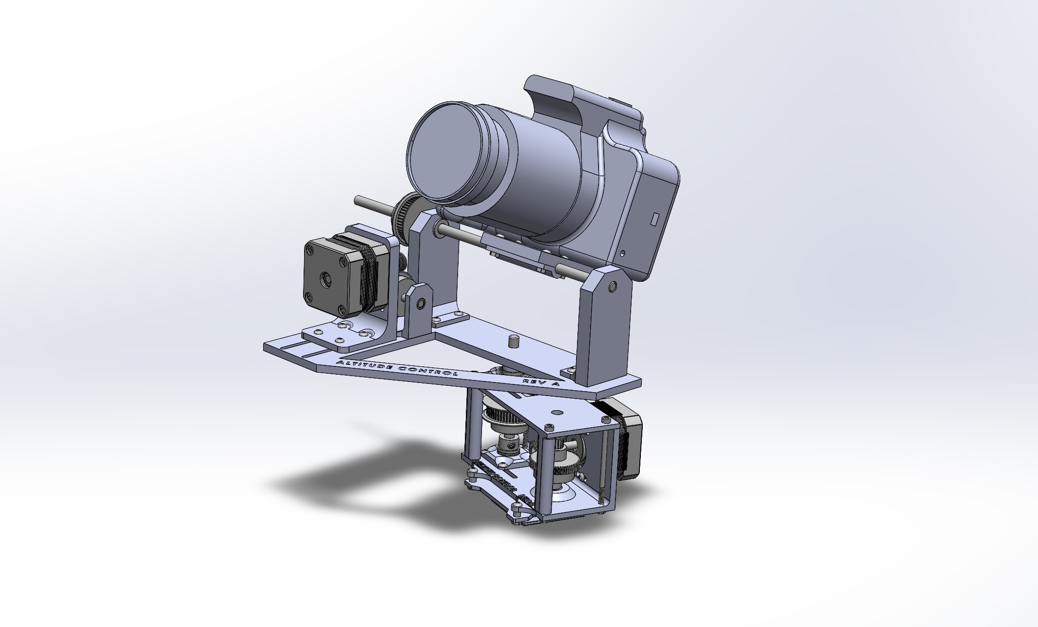
The azimuth (angle clockwise from north) and altitude (angle above horizon) components of the orientation of the camera require a high degree of precision, much higher than the 1.8° step angle of most stepper motors. To achieve the necessary precision, I designed two 180:1 gearboxes for each axis of rotation.
Azimuth Gearbox
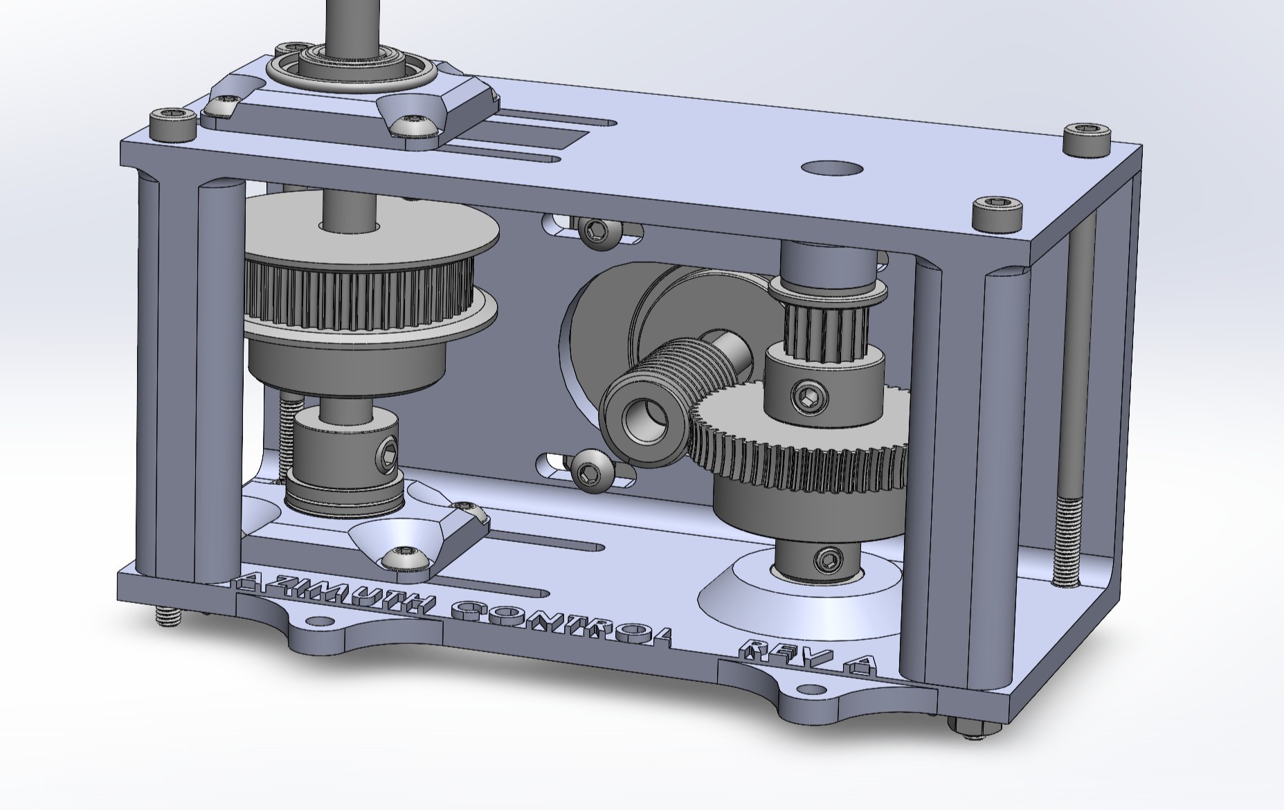
View of the entire azimuth gearbox assembly, minus the drive belt between the two axles.
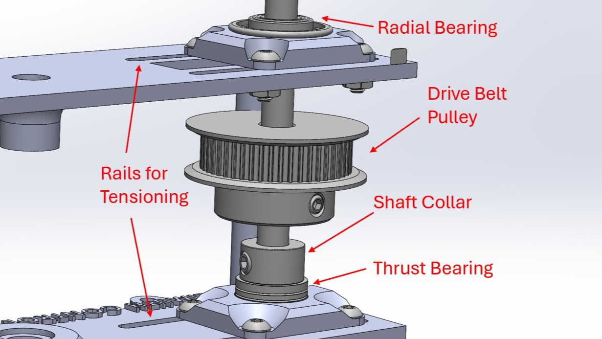
Cross-section of the load-bearing section of the azimuth gearbox.
Each gearbox uses a 60:1 worm gear connected to a 3:1 belt pulley system to achieve the desired gear ratio. Belts were chosen over traditional spur gears to reduce backlash and vibration. In hindsight, the added complexity and cost may not have been worth the benefit, as I had to design rails to allow the belts to be tensioned.
A selection of bearings were intentionaly chosen to support the load of the camera and altitude gearbox without introducing any play or vibration. A shaft collar directs downward force from the shaft to a thrust bearing, which rests on the 3D-printed base. To prevent any lateral displacement of the shaft, a radial bearing was placed as a second point of contact, further reducing excess play. Since the motor turns extremly slowly, sleeve bearings were chosen for the worm gear shaft due to their low cost and minimal complexity.
Altitude Gearbox
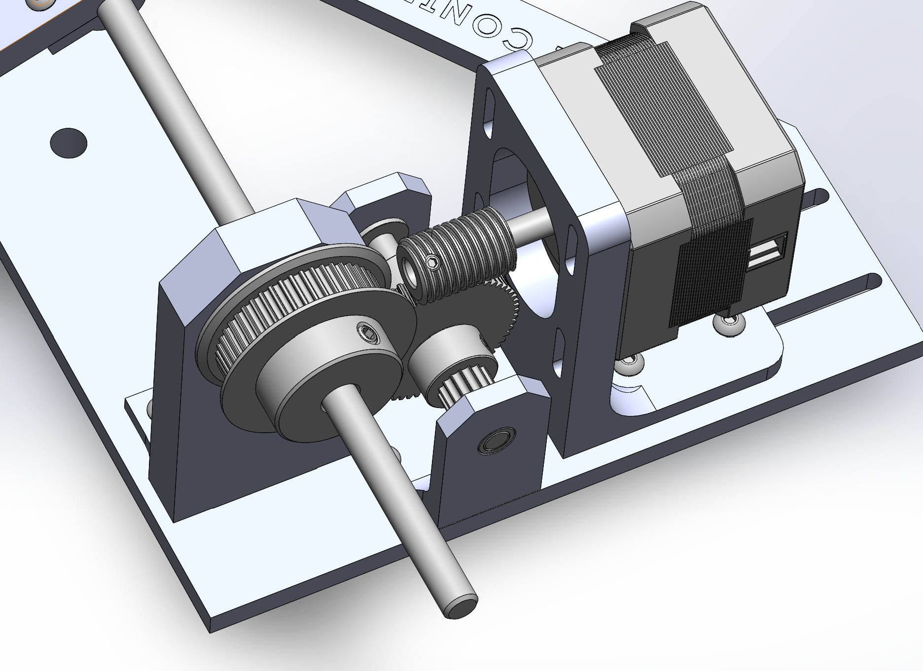
Drivetrain for the changing the camera's altitude (or pitch)
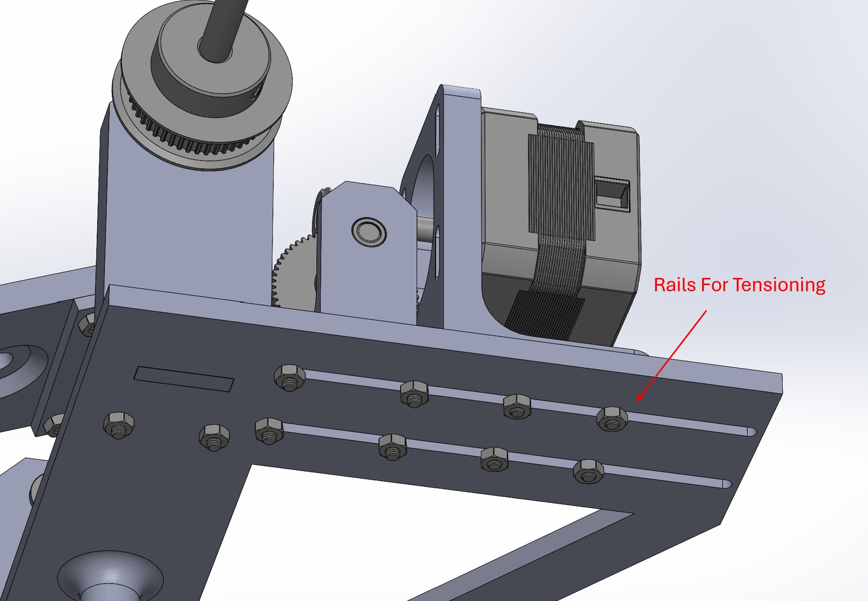
Rails support the worm gear and belt pulley to allow for easy tensioning
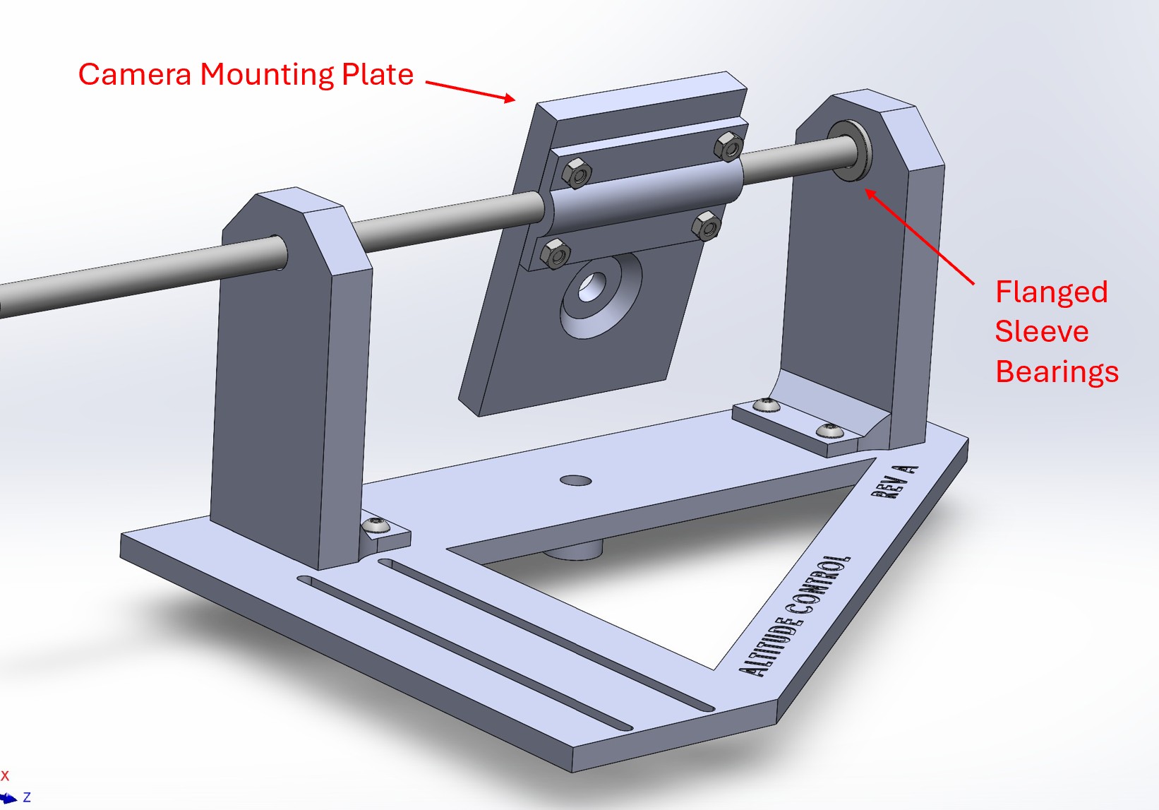
View of the camera mount plate and altitude shaft
A horizontal shaft allows the camera to pitch up and down. Since the shaft rotates very slowly and does not support a massive amount of weight, flanged sleeve bearings were chosen for their simplicity and low cost. Similar to the azimuth gearbox, a drive belt was used to step down the speed of rotation from the 60:1 worm gear. To allow the belt to be tensioned, the gearbox was mounted on rails to allow for slight adjustments before being locked in place with bolts.
The camera mount plate was designed so that, for low to mid elevation angles, the center of mass of the entire elevation assembly is relatively close to the azimuth shaft to reduce torque. Ideally, the altitude shaft would be coincident with the center of mass of the camera, but this would increase complexity and would be unnecessary, since the high gear ratio increases the torque of the motor by a factor of 180 (much more than enough to rotate the camera off-axis).
Control Software
Program Flow
The Raspberry Pi controls every aspect of taking long-exposure photos: It determines where the camera is looking and adjusts its position, controls the exposure settings, and saves each image after it is taken.
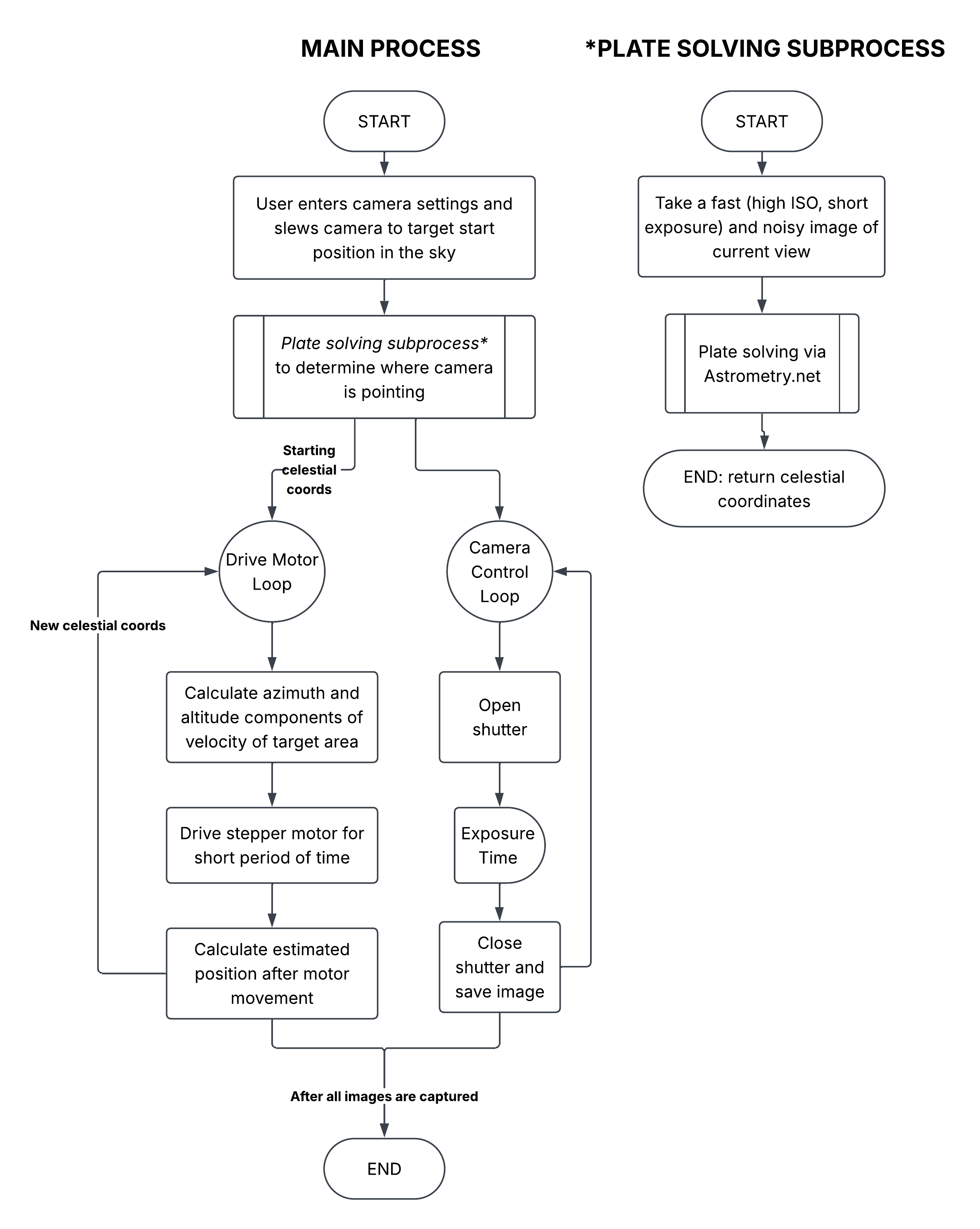
Flowchart of the control system for the gimbal
Plate Solving
The rate at which a particular star appears to move is determined by the observer's geographic location and the star's position in the sky at that given moment. The geographic coordinates of the user can be easily determined using GPS, but the exact position of the area of the sky that the camera is pointed at is less obvious. A process called plate solving takes an image of the night sky and compares it to a database of known star positions to determine the exact coordinates of the camera's field of view. Astrometry.net is an open-source plate solving program that I used to determine exactly where the camera is pointing, and using those coordinates to calculate the necessary speed each stepper motor should rotate.
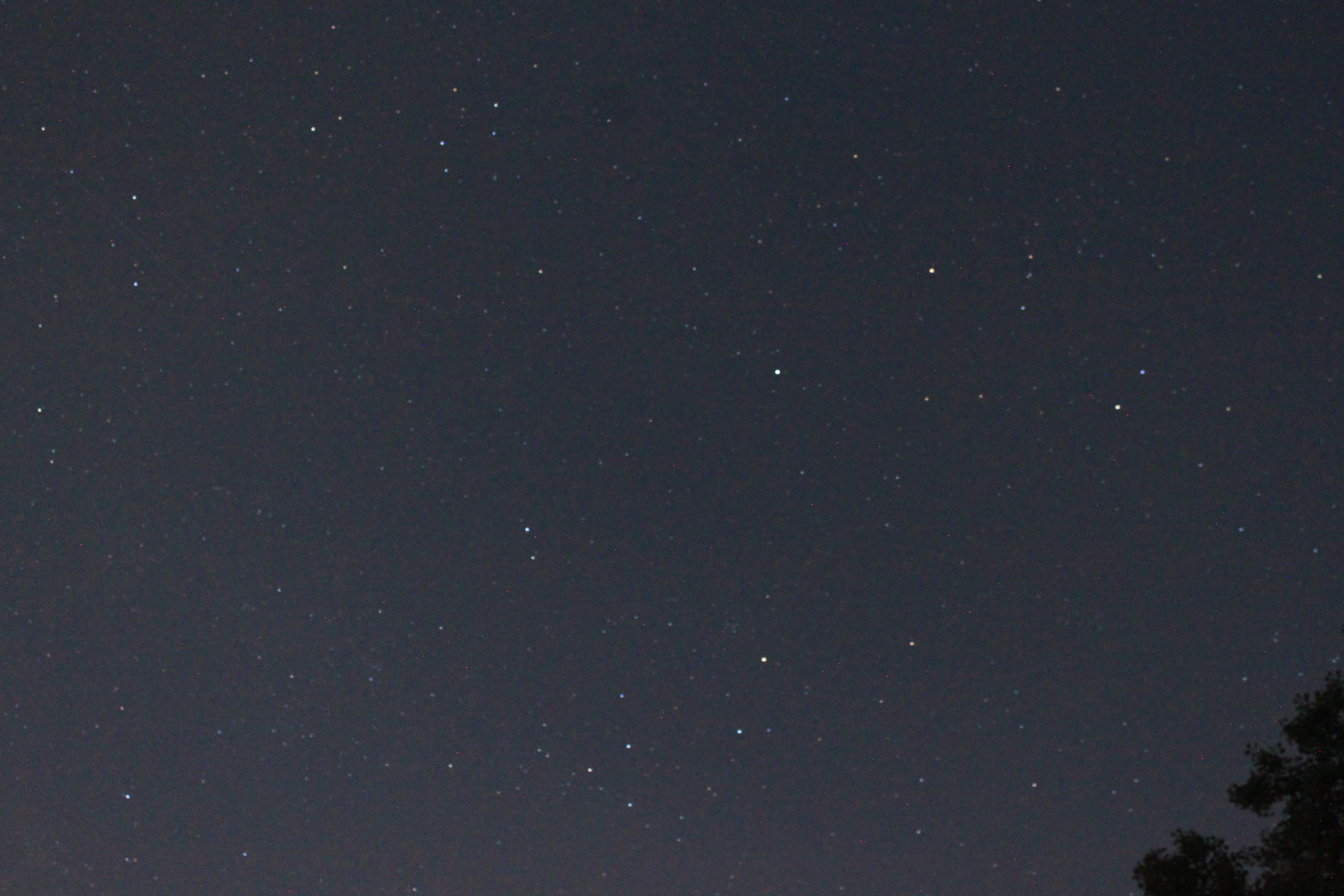
Before tracking, the camera captures a high-ISO, short-exposure image to quickly determine where it is looking.
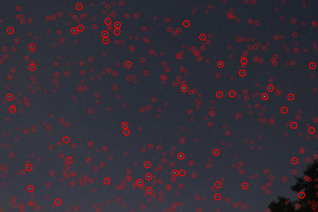
The plate solver finds the positions of stars in the image.
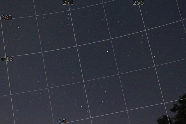
The plate solver uses known star positions to determine the exact celestial coordinates of the camera's field of view.
Results
Processed Images
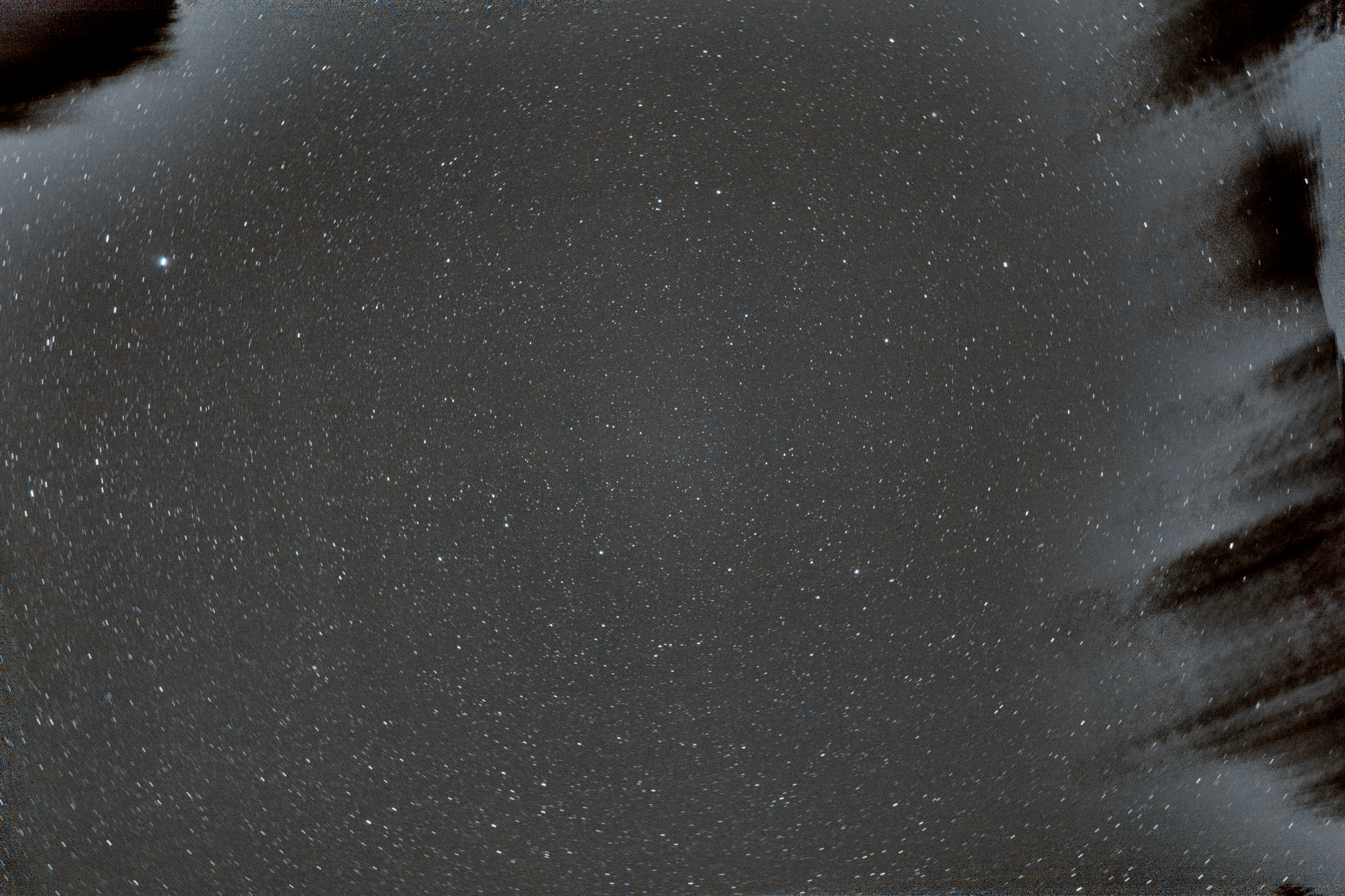
Composite of 40 × 45-second exposures (30 mins total)
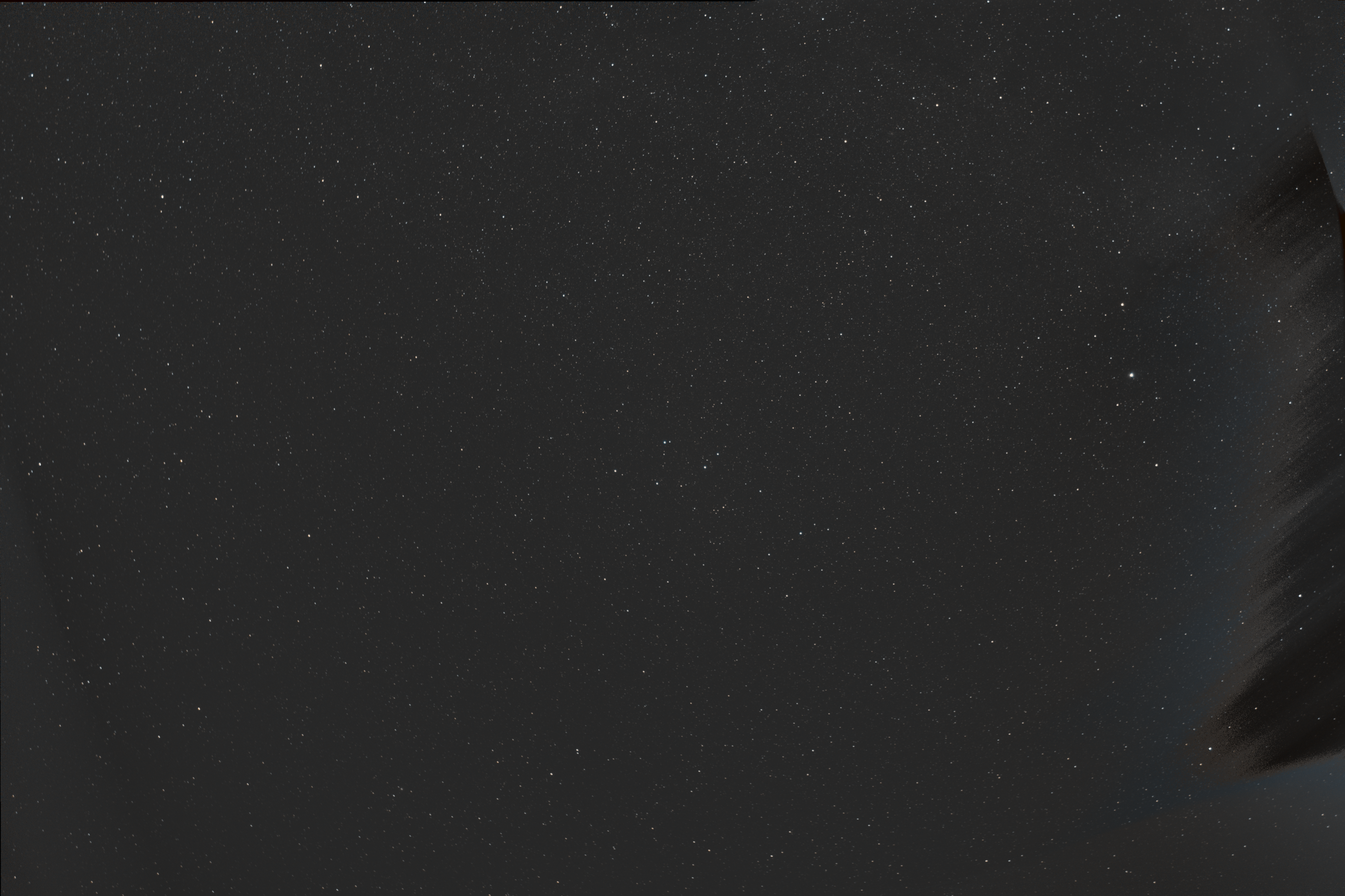
Composite of 240 × 30-second exposures (2 hours total)
These images demonstrate the gimbal's ability to track stars accurately over extended periods of time. The first image was composed of longer exposures over a shorter total time, which produced a slightly noisier image. The second image used shorter exposures over a longer total time, which produced a cleaner image with more detail. The artifacts on the edges of both images are the trees in my backyard, which slowly moved into frame as the night went on.
For a light-polluted suburban backyard surrounded by trees and a not-so-optimal view of the night sky, I was pleasantly surprised by these results and the number of distant stars I was able to capture.